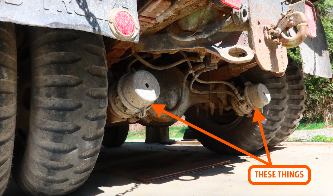
Here's What Those Big 'Bulbs' On Semi Trucks Are
David dives deeply into the inner workings of a truck's air brakes
Have you ever noticed two large "bulb" shaped canisters hanging off the rear axles of semi trucks? Here's what those are and how they work.
(We're taking an extra day today to celebrate Independence day. Enjoy some of our best stories from the last month or so.)
While I was in Washington fixing my 1958 Willys FC-170 back in April, my host, Tom Mansfield, showed me his incredible Ford C-600 dump truck, which used to serve Seattle City Light, the public utility charged with illuminating The Emerald City.
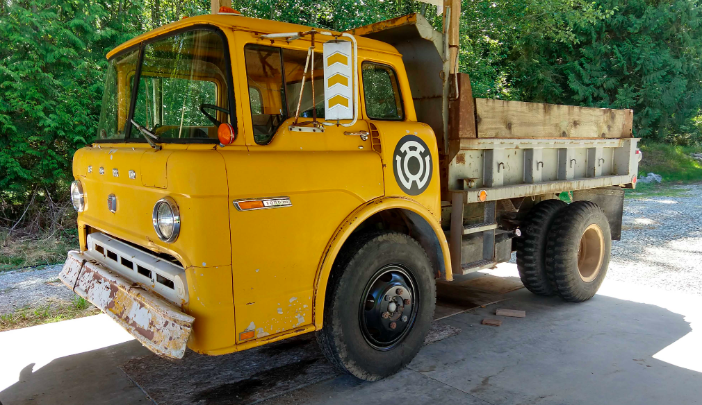
While spending my days wrenching on what seemed like a hopeless old Jeep, I had plenty of time to admire Tom's awesome yellow cab-over-engine truck. Two things that piqued my interest were the canisters located on the rear axle. I see such canisters all the time while driving behind big rigs on the highway, but I was never sure exactly what those canisters did or how they worked.
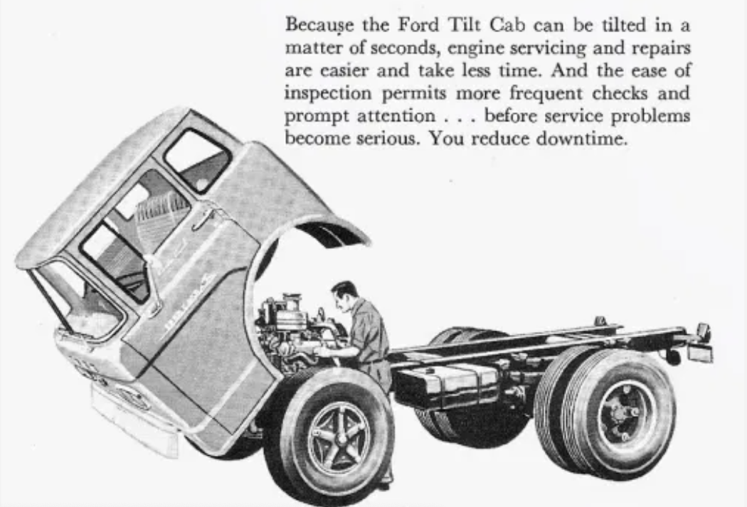
To walk me through it, Tom unlatched and then leaned the truck's cab forward — an operation that's fairly easy thanks to two big coil springs that help lift the cab from underneath.
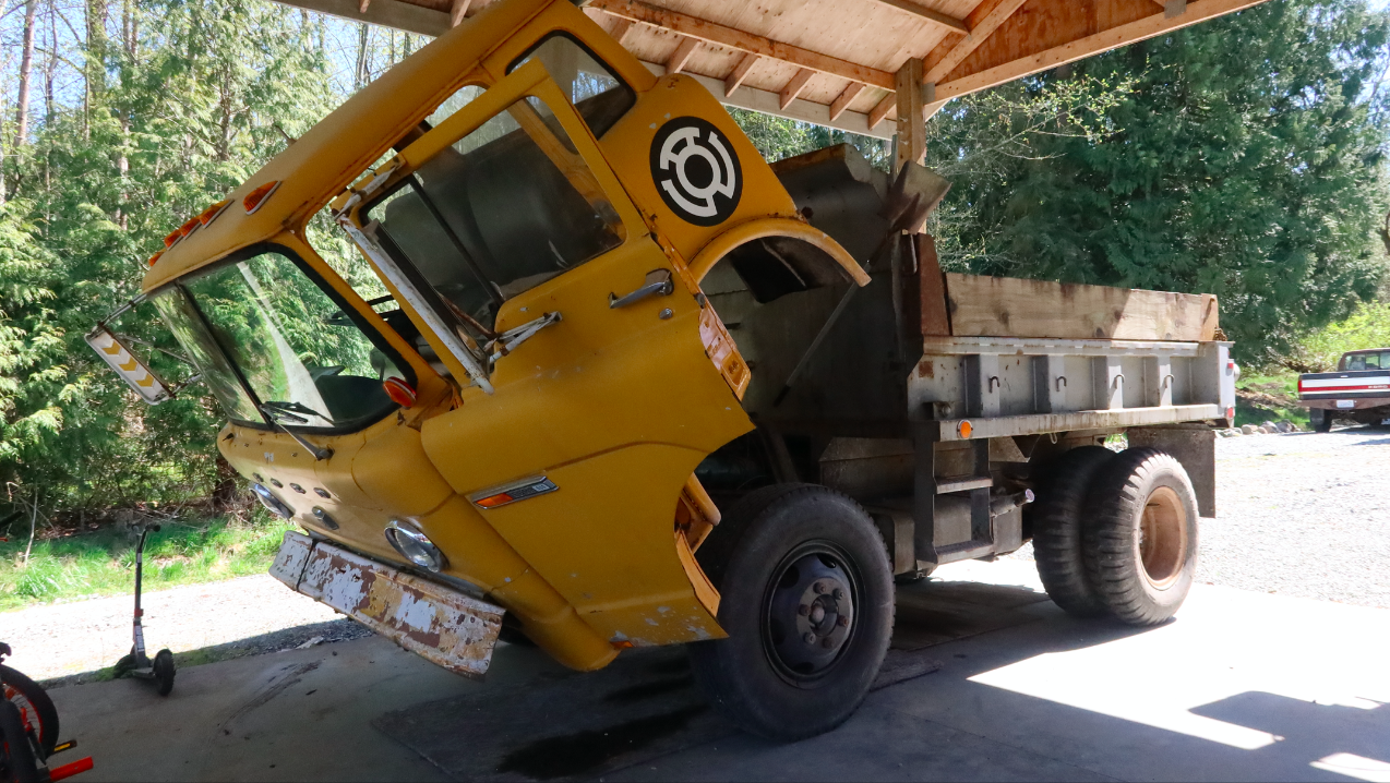
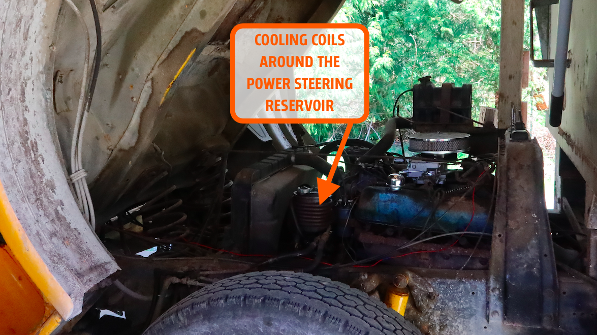
Tom pointed out the amazingly accessible 330-FT V8 engine (a beefed-up derivative of the 330-FE ("FE" for "Ford Edsel"), which is topped by a Motorcraft 2150 carburetor, and which spins a power steering pump that has a copper cooling pipe surrounding its reservoir (I mention this because I find it rather interesting; see below).
Also on the engine's accessory drive is a piston-style air compressor. This looks like a small motorcycle engine, except instead of air and fuel being the input and crankshaft rotation being the output, energy is fed to the crankshaft via a belt in order to push a piston to compress air, which is the output. That high-pressure air's job is to feed the air brakes; that's what the two big bulbs are on the rear axle (and also up front).
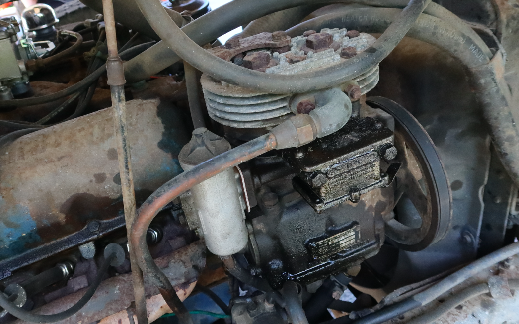
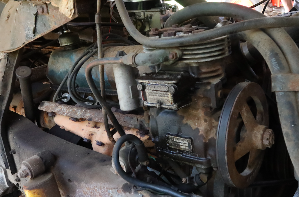
Of course, the squeezed air from the compressor doesn't go directly into those "bulbs." It first goes through a regulator, which modulates compressor output to keep system pressure at the right level (around 100 PSI); then air is routed through hoses and hard lines to two reservoirs tucked between the frame rails behind the rear axle. Those reservoirs, shown below, hold a large enough volume of compressed air to allow for multiple brake applications even if the compressor or supply line goes on the fritz. It's one of multiple failsafes in this system.
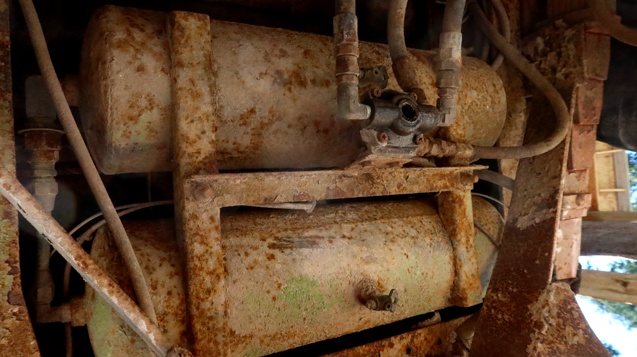
You'll notice that both tanks feature drain valves. These are there so that the moisture in the compressed air, which pools as water at the bottom of the tanks, can be removed from the system to prevent corrosion and ice buildup from rendering brakes useless. The tanks also contain safety valves that release air if the pressure exceeds a certain limit — usually roughly 150 psi.
Valves control the flow of compressed air from the tanks into the canisters/bulbs on the axle. Here's a look at one of the canisters:
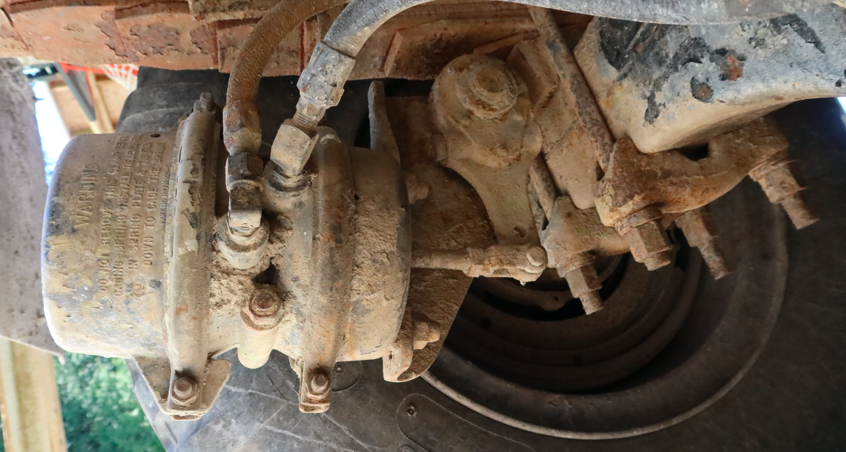
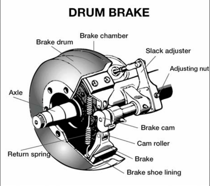
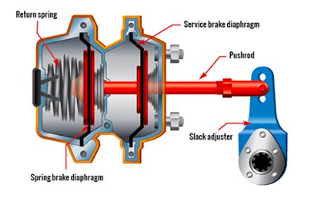
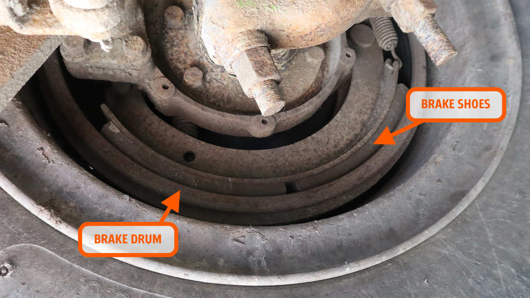
The "bulb," as I've been calling it, consists of two main chambers: The service brake chamber and the spring brake chamber. The service brake behaves basically like your normal brake on your car; it operates when the driver presses the brake pedal. On a vehicle with air brakes, the brake pedal is also called the foot valve or the treadle valve, since pressing the pedal actuates a valve that sends compressed air acting against the service brake diaphragm, pushing a pushrod, rotating a slack adjuster about a camshaft (the slack adjuster provides torque multiplication), ultimately rotating a cam that spreads brake shoes against a brake drum. This stops the truck.
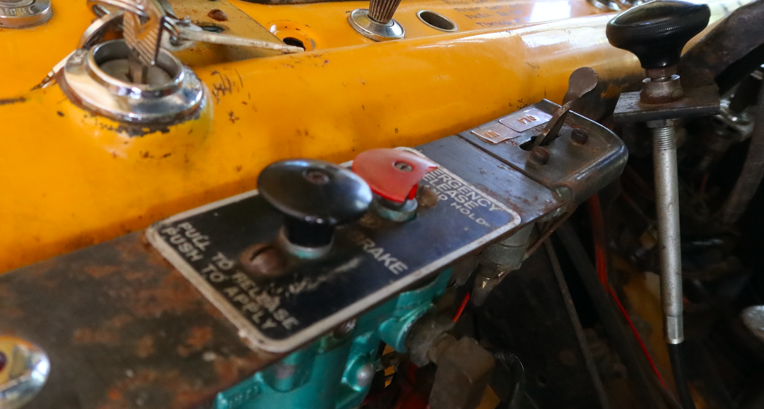
The spring brake is the park brake; it's called the spring brake because, unlike the service brake, the brake is actually actuated by a spring and not by positive air pressure. Pulling a knob like the one below actuates a valve and applies air pressure to the spring brake, releasing this brake. This means a leak in the air system — which would compromise your service brakes since those brake require air pressure to function — will actuate the park brake, making it act as an emergency brake. It's a failsafe.
Often times, you'll hear a big truck come to a stop followed by a loud hissing noise. That's the park brake being applied, the spring forcing the diaphragm towards the pushrod and air being forced out of the chamber. Per the 2005 Commercial Driver's License Manual posted by the Rhode Island DMV, when air pressure reaches roughly 20 to 30 psi, the spring brakes will be fully actuated.
Here's a look at the setup courtesy of Ontario, Canada's "The Official Air Brake Handbook." The image directly below shows the innards of the canister with the parking brake off (i.e. air has been pumped into the spring brake chamber, compressing the spring, pulling the pushrod, rotating the slack adjuster and camshaft, allowing the brake shoes to contract). Note that the service brake is engaged (i.e. the driver is depressing the brake pedal).
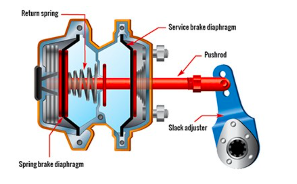
Here's what the setup looks like with the park brake engaged and air no longer forcing the spring brake diaphragm to the left against the spring. This means the pushrod is being forced to the right, pushing the slack adjuster, imparting a torque on the camshaft, forcing the brake shoes against the drums:
In case you're curious, here's a look at the parked C-600's brake shoe liner pushed up against the brake drum:
You can see how this all works in the video below. It's all quite exciting.
You may be wondering why this system is so different than what you've got in your car. Part of the reason, per a cursory Google search, has to do with the fact that traditional vehicle hydraulic brake systems are too vulnerable. A hole in a brake line or hose renders that entire brake system/subsystem useless. A hole in a pneumatic line or hose isn't as big of a deal, since there are tanks right near each brake, and the tanks hold enough air for multiple brake applications.
It's also worth mentioning that, when hooking up trailers to tractors, operators simply attach the tractor's brake system to that of the trailer via"glad hand" couplers. These are those twisted colorful hoses you see on the back of semi trucks between the cab and the trailer, and they're quick and easy to hook up.
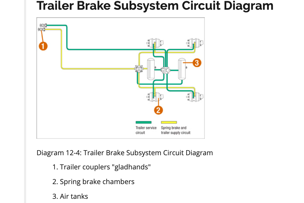
Here's a little video showing these hose attachments:
There's also a cost/weight advantage of pneumatic brakes, and of course, the system doesn't require a driver to apply much force to the brake pedal to create pressure to apply brakes.
You may be wondering why we haven't talked about disc brakes. It's because drum brakes are still popular among over-the-road trucks, because, well, they work well enough. Still, there are some air-powered disc brakes out there; here's a look at one design:
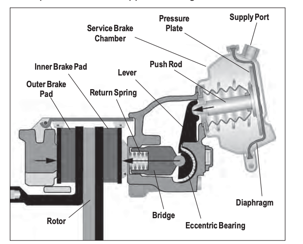
I've now spent nearly an entire day researching truck air brakes and, given that I could see myself spiraling down this rabbit hole for a solid week, I'm gonna have to cut myself off and leave it at this:
The answer to the question you were wondering about — What's the deal with the big bulbs on truck axles? — is that they're air brakes. They house air chambers that are fed by a reservoir and compressor, and that ultimately rotate a camshaft to spread brake shoes against a rotating drum, bringing the truck to a halt.
